Table of Contents
A cable route can fit neatly on a plan and still be impossible to install. Substation cable routing must account for cable ends, bending radius, pulling tension, support, segregation, water, fire barriers, construction sequence, and access for future work. A centerline drawn between two rooms is only the beginning.
This guide gives EPC designers, contractors, and owners a constructible workflow for substation cable routing. It covers route allocation, electromagnetic compatibility, trench design, equipment entries, spare capacity, and as-built inspection without relying on a generic percentage allowance.
Build routes from endpoints and the final cable schedule
Start with a controlled cable schedule listing tag, source, destination, circuit function, voltage, conductor count and size, shield or armor, outside diameter, minimum bend radius, pulling limit, fire classification, and termination type. Substation cable routing based on an early load list will miss the auxiliary and communication cables added later.
Locate the real entry point on each item of equipment. A transformer neutral box, switchgear bottom plate, relay panel top gland, and battery charger may face different directions. Trace each cable from gland to gland, including the vertical rise, termination loop, and space required by the installer.
- Approved equipment plans and sections
- Final cable schedule with diameters and weights
- Manufacturer bend and pulling limits
- Room, trench, duct-bank, and tray dimensions
- Construction joints and equipment installation sequence
- Fire compartments and environmental classifications
- Future feeders and reserved endpoints
Assign a route and support level to every cable, then calculate fill by usable dimensions rather than gross trench area. Keep a change log so late cable additions trigger a substation cable routing review instead of being placed wherever space remains.

Separate circuits by function and interference risk
Group cables by electrical function and susceptibility. High-current power circuits create electric and magnetic fields; protection, metering, communication, and low-level analog circuits can be sensitive. Substation cable routing should specify separation distance, barrier use, crossing angle, shield bonding, and any permitted exceptions.
| Circuit group | Primary routing concern | Review action |
|---|---|---|
| MV and LV power | Current rating, bend radius, heat, fault force | Check spacing, supports, pulling plan, and phase arrangement |
| Protection and control | Induced noise and common-cause damage | Define separation and controlled crossings |
| DC trip and close | Reliability during AC system faults | Protect routes and avoid unnecessary common exposure |
| Communications and fiber | Bend limit, physical protection, fire rating | Use compatible tray and termination practices |
| Earthing conductors | Continuity and electromagnetic behavior | Coordinate with the grounding design |
Route redundant protection or trip channels so one fire, flood, tray collapse, or excavation cannot defeat both where the reliability study requires physical diversity. Separation on adjacent tray tiers may not provide true route diversity if both pass through the same penetration.
Cross incompatible circuit groups deliberately, usually at a controlled angle where practicable, and avoid long parallel runs without review. Follow cable and system supplier instructions for screen bonding and earthing. The International Electrotechnical Commission and IEEE Standards Association publish relevant cable installation, EMC, and substation standards.
Prove pulling, bending, support, and fault restraint
Check each bend in three dimensions. A plan may show adequate radius while the cable must also rise into a gland plate. Large power cables need straight length for pulling grips and termination preparation. Substation cable routing should include pull direction, drum position, rollers, winch location, intermediate access, and maximum pulling tension.
Size supports for cable weight, installation load, spacing, and short-circuit forces where applicable. Select cleats and spacing for the prospective fault current and cable arrangement. Do not assume ordinary tray clips restrain single-core power cables during a fault.
Coordinate phase formation and transposition where required, and prevent ferromagnetic heating around single-core AC cable entries. Maintain manufacturer bend radius during storage, pulling, dressing, and final termination—not only on the drawing.
- Approve substation cable routing before embedded work begins.
- Check substation cable routing at every change of direction.
- Coordinate substation cable routing with equipment installation order.
- Protect substation cable routing through each fire boundary.
- Retain substation cable routing access for inspection and replacement.

Design trenches for water, fire, and safe access
Trenches need slope, drains or sumps, water stops, covers, load rating, ventilation where relevant, and safe access. Substation cable routing below grade must consider groundwater, surface runoff, oil containment boundaries, rodents, corrosion, and the possibility that a drain becomes blocked.
Define fire zones and penetration systems before cables are pulled. Fire stops must be compatible with cable jackets, wall ratings, future additions, and inspection. Avoid filling a penetration so completely that the next approved cable cannot be installed without destroying the system.
Keep covers removable without lifting installed equipment or permanent piping. Provide safe lifting points and manageable cover sizes. A trench that cannot be inspected will accumulate water, debris, and unrecorded cable crossings.
Coordinate entries before concrete and gland plates are fixed
Freeze foundation openings, sleeves, embedded conduits, and gland plates only after equipment and cable data are coordinated. Substation cable routing errors at this stage create sharp offsets, field-cut plates, reduced sealing, or bend-radius violations that are expensive to correct after concrete is poured.
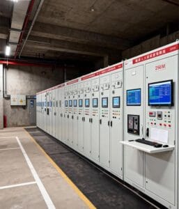
Check transformer marshalling boxes, switchgear base channels, control-building raised floors, battery-room boundaries, fire seals, and external yard duct banks together. Coordinate with structural reinforcement, drainage pipes, HVAC ducts, earthing conductors, and door access.
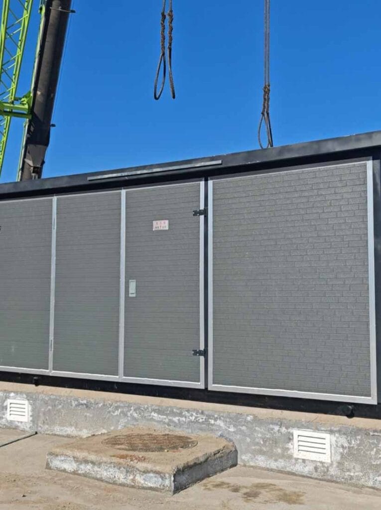
Our relevant project references include box-type substations, power-distribution equipment, EPC and engineering services, and the technical contact page. Share layouts and the cable schedule when requesting a substation cable routing review.

Reserve future capacity that installers can actually use
A spare percentage is useful only when the remaining path is continuous, accessible, and large enough for the future cable. Reserve tray width, support capacity, bend space, sleeve area, fire-stop modules, gland-plate positions, and termination space. Mark the intended future feeders on drawings.
Do not place all spares at one easy section while downstream bends and penetrations are full. Simulate the largest planned future pull through the entire substation cable routing path. Provide draw wires or access points for ducts and protect unused sleeves against water and pests.
Review cable ampacity after grouping and future fill. Added circuits can raise thermal mutual heating. The NFPA codes and standards program and NEMA standards resources provide additional references for projects using North American requirements; the adopted local code remains controlling.
Inspect and record the as-built route
Inspect trenches, trays, ducts, supports, cleats, labels, penetrations, bonding, seals, drainage, and covers before they are concealed. Confirm cable tags at both ends and intermediate access points. Record approved deviations from substation cable routing drawings while the installation is visible.
Test cable and screen continuity as specified, verify separation at congested crossings, and photograph each fire stop and embedded entry. Update plans, sections, cable schedules, pull records, and penetration registers. Handover should state remaining usable capacity, not simply “spare provided.”
The OSHA electrical resources offer useful safety context where applicable. Installation and inspection must also follow local confined-space, lifting, excavation, electrical, and fire-safety rules.
- Verify substation cable routing against the final schedule.
- Inspect substation cable routing before covers and fire stops close.
- Record substation cable routing deviations with dimensions.
- Confirm substation cable routing spare capacity end to end.
- Keep substation cable routing drawings synchronized with cable tags.
Frequently asked questions
How much spare tray space should a substation have?
Set it from identified future circuits and usable end-to-end space. A nominal percentage alone does not prove that large cables can pass bends and penetrations.
Can control and power cables share a trench?
They may share a structure when the adopted rules, separation, barriers, EMC study, and fire strategy permit it; define the arrangement explicitly.
What controls the minimum cable bend radius?
Use the cable manufacturer’s limit for the specific cable and installation condition, including pulling and final installed radius.
Why are cable trenches often wet?
Poor slope, blocked drainage, groundwater, open entries, or missing water stops can admit and retain water. Design and inspect the full drainage path.
What must an as-built cable record contain?
Show routes, levels, entries, supports, penetrations, tags, approved deviations, spare capacity, fire stops, and concealed-work photographs.
Successful substation cable routing is visible in construction: every pull is possible, each cable reaches its gland without abuse, sensitive circuits are protected, water and fire boundaries remain controlled, and future capacity is genuinely usable.