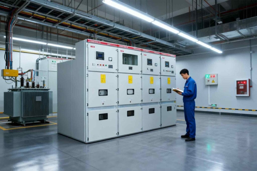
Medium voltage switchgear maintenance should protect three things: personnel, equipment, and continuity of power. It should not be reduced to cleaning cabinets once a year or testing every component at the same fixed interval.
A useful maintenance program combines equipment design, operating duty, environmental conditions, previous test results, fault history, manufacturer instructions, and the consequences of failure. Two identical switchgear lineups may require different maintenance frequencies when one operates in a clean electrical room and the other is exposed to dust, humidity, frequent breaker operations, or heavy industrial loads.
Electrical work on medium-voltage equipment must be planned and performed by qualified personnel under the applicable laws, site procedures, and equipment instructions. This article provides a planning framework rather than a universal field-testing procedure.
Table of Contents
Why Medium Voltage Switchgear Maintenance Matters
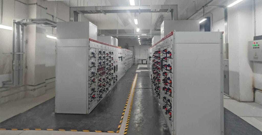
Medium-voltage switchgear controls, protects, isolates, and distributes power to transformers, motors, production lines, substations, and other critical loads. A defect in one compartment can affect far more than the feeder where it begins.
Possible consequences of poor maintenance include:
- Failure of a circuit breaker to open during a fault
- Unwanted tripping caused by a control-circuit problem
- Overheating at busbar or cable joints
- Insulation breakdown
- Failure of mechanical or electrical interlocks
- Inaccurate current or voltage signals
- Incorrect protection relay operation
- Difficulty racking a withdrawable breaker
- Loss of auxiliary power
- Arc-flash or electric-shock exposure
- Extended production downtime
- Damage that spreads to adjacent compartments
Maintenance cannot eliminate every failure. It can, however, identify developing problems before they become operational emergencies and confirm that protective functions remain available when required.
For metal-enclosed AC switchgear above 1 kV and up to 52 kV, the current consolidated edition of IEC 62271-200 provides the relevant product-standard framework. General requirements for AC switchgear and controlgear are addressed by IEC 62271-1. These standards establish equipment requirements, but the site still needs a maintenance strategy suited to its actual installation and duty.
Do Not Use One Universal Maintenance Interval
A statement such as “service the switchgear every year” is easy to schedule but may be technically incomplete.
The maintenance interval should be influenced by:
- Equipment manufacturer and model
- Switchgear age
- Circuit-breaker type
- Number of mechanical operations
- Number and severity of fault interruptions
- Rated current and normal loading
- Load variation
- Ambient temperature
- Humidity and condensation
- Dust and airborne contamination
- Corrosive or saline atmosphere
- Ventilation performance
- Presence of insects or small animals
- Previous inspection findings
- Previous test trends
- Protection operations
- Equipment criticality
- Availability of redundant feeders
- Planned production shutdowns
- Applicable regulations and insurance requirements
A circuit breaker that has interrupted a high fault current may need immediate inspection even if its scheduled maintenance date is months away. Conversely, intrusive disassembly of reliable equipment without technical justification can introduce loose connections, damaged seals, incorrect adjustments, or foreign material.
The right question is not only “When was the last service?” It is also “What has happened to the equipment since then?”
Build a Switchgear Maintenance Baseline
A strong program begins with an accurate equipment baseline. Without it, technicians may collect readings that cannot be interpreted or compared.
The baseline should include:
- Single-line diagram
- Switchgear model and serial numbers
- Rated voltage
- Rated normal current
- Short-time withstand rating
- Protection device models
- Relay setting files
- Current transformer ratios and classes
- Voltage transformer data
- Control and auxiliary voltage
- Circuit-breaker model
- Interrupting medium
- Breaker operating mechanism
- Operation counter readings
- Original factory test records
- Commissioning test results
- Previous maintenance reports
- Wiring diagrams
- Mechanical interlocking diagrams
- Manufacturer manuals
- Recommended lubricants
- Spare-parts list
- Modification history
- Fault and trip history
Commissioning results are especially valuable because they provide reference values for later comparison. A contact-resistance result that appears acceptable in isolation may still deserve investigation if it has doubled since commissioning or differs substantially from the other phases.
If baseline records are missing, the first maintenance outage should be used to establish a documented condition reference.
Plan Electrical Safety Before Opening the Equipment
Maintenance planning starts before tools or test instruments enter the switchgear room.
The work package should address:
- Equipment identification
- System operating condition
- Isolation boundaries
- Alternative power sources
- Backfeed risk
- Stored electrical and mechanical energy
- Lockout and tagout requirements
- Voltage testing
- Earthing or grounding requirements
- Adjacent energized compartments
- Arc-flash assessment
- Required personal protective equipment
- Access control
- Test-equipment suitability
- Emergency procedures
- Restoration and energization sequence
De-energization should not be assumed merely because a breaker is open. The isolation state, possible secondary sources, voltage-transformer circuits, control supplies, bus couplers, generators, capacitors, and cable backfeed paths must be considered.
The OSHA electric-arc flash guidance explains that equipment that has been de-energized but not correctly locked or tagged must still be treated as energized under the cited U.S. requirements. Projects outside the United States must apply the corresponding national regulations and site safety rules.
Maintenance should also consider the hazards created by withdrawing or inserting a breaker, operating an earthing switch, opening a compartment, or performing diagnostic measurements near energized conductors.
Divide Maintenance Into Four Levels
A practical medium voltage switchgear maintenance program can be organized into four levels.
Routine Operational Inspection
This is completed without opening hazardous compartments or interrupting normal operation. It focuses on visible, audible, and recorded signs of deterioration.
Typical checks include:
- Alarm status
- Protection relay indications
- Trip-circuit supervision
- Breaker position indication
- Abnormal noise
- Unusual odor
- External surface temperature
- Room temperature and humidity
- Ventilation condition
- Water ingress
- Condensation
- Dust accumulation around ventilation paths
- Signs of corrosion
- Damaged doors or seals
- Counter readings
- Space-heater operation
- Battery or DC system alarms
Planned Preventive Maintenance
This is completed during a controlled outage. It may include cleaning, mechanical inspections, torque verification where required, circuit-breaker servicing, insulation checks, control-circuit testing, protection testing, and functional verification.
Condition-Based Diagnostic Work
This is triggered by trends or abnormal findings rather than a calendar date. Examples include thermography, partial-discharge assessment, detailed contact analysis, insulation diagnostics, or investigation of repeated control failures.
Post-Event Inspection
This follows conditions such as:
- Fault interruption
- Protection trip
- Internal flashover
- Flooding or water ingress
- Severe condensation
- Overheating
- Smoke or burning odor
- Earthquake
- Impact during transport
- Major upstream disturbance
- Breaker failure
- Abnormal switching operation
Post-event inspection should be defined by the event, affected equipment, manufacturer guidance, and engineering assessment.
Medium Voltage Switchgear Maintenance Schedule Example
The following schedule is an initial planning example, not a universal requirement.
| Maintenance stage | Typical activities | Interval or trigger |
|---|---|---|
| Operational observation | Check alarms, indications, room condition, noise, odor and visible abnormalities | Daily, weekly or according to site operating practice |
| External inspection | Review doors, labels, heaters, ventilation, corrosion, water ingress and housekeeping | Monthly or quarterly |
| Condition review | Analyze loading, trip records, breaker counts, thermal trends and diagnostic alarms | Quarterly or semiannually |
| Planned outage inspection | Inspect, clean, test and functionally verify the equipment | Based on risk, manufacturer guidance and site history |
| Breaker mechanism service | Inspect mechanism, lubrication, coils, latches, timing and wear indicators | Based on time, operation count and interrupting duty |
| Protection-system testing | Verify relay functions, trip circuits, current and voltage inputs and settings | Based on the protection program and applicable rules |
| Detailed diagnostic assessment | Perform targeted insulation, partial-discharge, contact or timing tests | When trends or risk justify the work |
| Post-fault inspection | Assess breaker, busbars, cables, insulation, protection records and affected compartments | After significant fault interruption or abnormal event |
| Major refurbishment review | Evaluate components, mechanisms, insulation and obsolete parts | Based on condition, age, duty and supportability |
Intervals should be shortened when the environment is severe, operation frequency is high, previous results are deteriorating, or the consequences of failure are substantial.
Start With the Switchgear Room
Some equipment problems originate outside the cabinet.
Before inspecting internal components, review the room or substation for:
- Roof leaks
- Pipework above equipment
- Wall or floor water ingress
- Blocked ventilation
- Failed air conditioning
- Excessive temperature
- High humidity
- Condensation
- Dust
- Chemical vapors
- Salt contamination
- Rodent or insect activity
- Inadequate lighting
- Obstructed escape routes
- Storage of unrelated materials
- Insufficient access clearance
- Damaged cable trenches
- Flooding risk
- Failed space heaters
- Loose floor panels
- Open cable entries
Environmental control can be more effective than repeatedly cleaning contamination from the switchgear.
The service conditions assumed by the equipment design should be compared with the real installation. For example, IEC 62271-1 identifies defined normal service conditions and addresses altitude considerations above 1,000 meters. Equipment installed outside its specified temperature, altitude, humidity, or pollution conditions may require a design review rather than only more frequent cleaning.
Visual Inspection of the Switchgear Lineup
During a planned outage and after the equipment has been made safe, the inspection should cover the entire lineup systematically.
Look for:
- Discoloration
- Carbon deposits
- Tracking marks
- Cracked insulation
- Damaged barriers
- Loose hardware
- Corroded parts
- Water staining
- Dust accumulation
- Foreign objects
- Signs of overheating
- Damaged shutters
- Distorted busbar supports
- Missing fasteners
- Worn mechanical linkages
- Damaged wiring
- Loose terminal ferrules
- Rodent damage
- Blocked ventilation
- Defective compartment lighting
- Damaged labels
- Unsealed cable entries
- Oil or grease contamination
- Incorrect component substitutions
Photographs should be taken before cleaning when unusual deposits, damage, or overheating are found. Removing the evidence too early can make root-cause analysis more difficult.
Cleaning methods must be compatible with the insulation, enclosure, components, and manufacturer instructions. Aggressive solvents, high-pressure air, uncontrolled vacuum tools, or lint-producing materials may cause additional problems.
Inspect Busbars and Primary Connections
Busbars and primary connections carry high current and experience mechanical forces during faults. Problems may develop at joints, cable terminations, breaker contacts, and transitions between transport sections.
Review:
- Busbar surface condition
- Joint discoloration
- Plating condition
- Flexible connection condition
- Support insulator integrity
- Phase barriers
- Joint hardware
- Contact pressure arrangements
- Evidence of movement
- Clearance between conductors
- Earthing connections
- Neutral conductors where installed
- Transport-section joints
- Cable-to-bus connections
Bolted connections should not be tightened indiscriminately. The correct procedure depends on the joint design, fastener system, material, surface treatment, and manufacturer instructions. Unnecessary retightening can damage plated surfaces, overstress hardware, or produce inconsistent contact pressure.
Where torque verification is required, use approved values, calibrated tools, and a traceable record. If a joint shows thermal damage, investigation should extend beyond tightening to include contact surfaces, conductor condition, alignment, loading, and possible insulation damage.
Use Thermography as a Trend Tool
Infrared thermography can identify abnormal heating while equipment is carrying load. It can be useful for detecting:
- High-resistance connections
- Uneven phase loading
- Overloaded conductors
- Deteriorating cable terminations
- Poor contact engagement
- Abnormal breaker connections
- Heating in auxiliary equipment
However, thermography has limitations.
A meaningful survey should record:
- System load
- Phase currents
- Ambient temperature
- Equipment configuration
- Access method
- Camera settings
- Emissivity assumptions
- Comparison between phases
- Previous images
- Inspection location
- Severity criteria
Low loading can hide a developing resistance problem. A normal external cabinet temperature does not prove that sealed internal contacts are healthy. Thermal windows and viewing arrangements must also be evaluated for their suitability and safety.
Thermography should supplement inspection and testing rather than replace them.
Inspect and Test the Circuit Breaker
The circuit breaker is one of the most mechanically active components in the switchgear.
For withdrawable equipment such as KYN28 high voltage switchgear, the maintenance review may include the breaker truck, primary disconnects, secondary plug, shutters, racking mechanism, position indications, interlocks, and earthing arrangements.
Typical circuit-breaker checks include:
- General cleanliness
- Insulation condition
- Primary contact wear
- Contact fingers
- Springs and linkages
- Bearings and pivots
- Lubrication condition
- Opening coil
- Closing coil
- Motor-charging mechanism
- Latches
- Auxiliary switches
- Operation counter
- Mechanical position indication
- Secondary connections
- Manual charging and operation
- Electrical opening and closing
- Anti-pumping function
- Trip-free operation
- Racking movement
- Service, test, and disconnected positions
For AC circuit breakers above 1,000 V, the applicable product-standard framework includes IEC 62271-100:2021+AMD1:2024.
Mechanical Timing and Motion Tests
Timing tests can identify changes in opening time, closing time, pole synchronism, contact travel, or mechanism behavior. Results should be compared with:
- Manufacturer limits
- Commissioning values
- Previous maintenance results
- Results from equivalent poles
- Results from similar breakers
A single timing number without a reference or acceptance basis has limited value.
Contact Resistance
Contact-resistance testing can help identify deteriorating joints or contacts. Interpretation should consider test current, instrument method, temperature, connection location, and repeatability.
Investigate:
- Large differences between phases
- Significant change from baseline
- Unstable readings
- Results outside manufacturer limits
- Correlation with thermal findings
- Visible wear or contamination
Do not apply one universal micro-ohm limit to every breaker and switchgear design.
Vacuum Interrupter Assessment
For vacuum circuit breakers, the interrupter condition must be assessed using methods approved for the specific breaker. Visual inspection alone cannot confirm vacuum integrity.
Any withstand or integrity testing should follow the manufacturer’s specified test voltage, waveform, duration, connection method, and safety precautions. Applying an unsuitable test method can damage equipment or produce misleading conclusions.
Operation count is also relevant, but it is not the only indicator. Fault interruptions, current magnitude, contact wear, mechanism condition, and manufacturer-defined duty limits must be considered together.
Check Shutters, Racking and Earthing Interlocks

Mechanical and electrical interlocks help prevent unsafe operations, but they can deteriorate through wear, misalignment, contamination, incorrect adjustment, or unauthorized modification.
Verify functions such as:
- Breaker cannot be moved incorrectly while closed
- Breaker cannot close between defined positions
- Shutters operate correctly
- Earthing switch position is correctly indicated
- Earthing switch operation follows the designed sequence
- Doors cannot be opened in prohibited conditions
- Breaker position contacts correspond with the mechanical position
- Secondary plug engagement is correct
- Mechanical key interlocks function as intended
- Electrical permissives and blocking signals operate correctly
Do not defeat an interlock merely to complete a test. If a functional test requires a special procedure, use the manufacturer-approved method and return all devices to their normal state afterward.
Evaluate Insulation Condition Carefully
Insulation deterioration can be caused by:
- Moisture
- Condensation
- Dust
- Salt
- Chemical contamination
- Thermal aging
- Electrical tracking
- Loose conductive particles
- Mechanical damage
- Insects or animals
- Excessive test stress
- Surface discharge
- Inadequate clearances
Possible assessment methods include:
- Visual inspection
- Insulation-resistance measurement
- Dielectric testing
- Partial-discharge assessment
- Surface condition examination
- Humidity and contamination review
Test results must be interpreted according to the equipment design, temperature, humidity, test method, manufacturer criteria, and baseline data.
Low insulation resistance does not automatically identify the defective component. The circuit may need to be divided into smaller sections so that cables, transformers, voltage transformers, surge arresters, and switchgear insulation can be assessed separately.
Sensitive electronic devices and connected equipment should be isolated when required by the approved test procedure.
When Is Partial-Discharge Monitoring Useful?
Partial discharge can indicate localized electrical activity within or around insulation. It may develop at voids, interfaces, contaminated surfaces, sharp conductive points, cable terminations, or damaged insulation.
Potential methods include:
- Transient earth voltage detection
- Ultrasonic detection
- High-frequency current transformer measurements
- UHF methods
- Conventional offline measurements
- Permanently installed monitoring systems
No single method detects every discharge source equally well. Results can also be affected by external interference.
A partial-discharge indication should be evaluated using:
- Signal pattern
- Phase relationship
- Location
- Trend over time
- Operating voltage
- Load
- Humidity
- Equipment type
- Background noise
- Correlation with thermal or visual findings
A one-time screening result should not automatically be treated as proof of imminent failure. Equally, a rising or repeatable signal should not be ignored because the equipment remains operational.
Condition monitoring is most useful when it supports a defined decision: continue operating, increase monitoring, schedule an outage, complete further diagnostics, repair, or replace.
Inspect Cable Compartments and Terminations
Cable terminations are common points of electrical and mechanical stress.
Check:
- Cable support
- Bending radius
- Phase identification
- Termination cleanliness
- Stress-control components
- Sealing
- Earthing or bonding
- Screen connections
- Clearances
- Moisture
- Tracking
- Cracks
- Discoloration
- Signs of movement
- Cable-entry plates
- Foreign objects
- Surge arresters where installed
- Current-transformer positioning
Cable weight should not impose unacceptable mechanical force on switchgear terminals. If a termination has overheated, the cable conductor, lug, contact surfaces, insulation, loading, and installation workmanship should all be assessed.
Cable tests and switchgear tests should be coordinated. Test voltages suitable for one component may not be suitable for every connected device.
Verify Current and Voltage Transformers
Current transformers and voltage transformers supply protection and metering information. A primary circuit can be healthy while incorrect secondary signals cause false tripping, failure to trip, or inaccurate measurement.
Review:
- Nameplate and ratio
- Polarity
- Accuracy class
- Wiring
- Terminal tightness
- Earthing arrangement
- Shorting links
- Fuse condition
- Secondary isolation devices
- Physical damage
- Contamination
- Overheating
- Drawings and labels
- Test-switch condition
Current-transformer secondary circuits must never be opened carelessly while primary current is flowing. Voltage-transformer circuits require appropriate isolation and fuse procedures.
After maintenance, verify that all shorting links, test switches, fuses, and terminal connections have been returned to the approved operating configuration.
Test Protection Relays and Trip Circuits
A relay display showing “healthy” does not prove that the complete protection chain will clear a fault.
The full trip path can include:
- Current or voltage transformer
- Secondary wiring
- Test switch
- Protection relay
- Output contact
- Lockout or auxiliary relay
- DC supply
- Breaker trip coil
- Mechanical trip mechanism
- Circuit breaker
- Status feedback
- Alarm or communication system
Maintenance may include:
- Relay self-diagnostic review
- Event-record retrieval
- Setting comparison
- Secondary injection
- Pickup and timing verification
- Logic testing
- Trip-circuit supervision
- Breaker trip testing
- Alarm testing
- Interlocking tests
- Communication checks
- Time synchronization
- Current and voltage input verification
- DC supply checks
- Battery condition review
Relay settings must be controlled as engineering documents. Changes should identify the reason, calculation reference, approving person, date, and final uploaded setting file.
A successful secondary-injection test verifies only the tested portion of the system. End-to-end or primary-injection testing may be needed when the objective is to verify a larger part of the protection chain.
Check the DC and Auxiliary Power Systems
Many switchgear failures originate in low-voltage control circuits rather than in the primary conductors.
Inspect:
- Station batteries
- Battery charger
- DC distribution board
- DC voltage
- Ground-fault monitoring
- Closing and tripping circuits
- Spring-charging motor supply
- Space-heater supply
- Relay auxiliary supply
- Panel lighting
- Control fuses
- Miniature circuit breakers
- Terminal blocks
- Wiring insulation
- Auxiliary relays
- Communication power supplies
A breaker with a healthy primary circuit may still fail to open if the trip coil, DC supply, wiring, or auxiliary contacts are defective.
Control-circuit testing should include realistic functional sequences rather than only continuity measurements.
What to Inspect After a Fault Interruption
After a significant fault, do not return equipment to service based solely on a visual glance or a successful breaker close command.
The engineering review should establish:
- Fault type
- Fault magnitude
- Fault duration
- Breaker interrupting duty
- Protection operation
- Relay event records
- Disturbance records
- Breaker operation count
- Upstream and downstream device operation
- Location of the fault
- Possible through-fault stress
- Manufacturer inspection requirements
The affected breaker may require inspection of contacts, interrupters, operating mechanism, insulation, primary disconnects, and control circuits.
Also inspect adjacent equipment for:
- Busbar movement
- Damaged supports
- Carbon deposits
- Pressure effects
- Loose connections
- Cable damage
- Arc products
- Enclosure distortion
- Loss of insulation integrity
The root cause must be identified before re-energization. Replacing a tripped fuse, resetting a relay, or closing the breaker without understanding the event can expose the system to a repeated and potentially more severe failure.
Use Test Results as Trends, Not Isolated Pass/Fail Numbers
A condition-based program depends on repeatable data.
For each test, retain:
- Equipment identification
- Serial number
- Test date
- Operating condition
- Ambient temperature
- Humidity
- Test instrument
- Calibration status
- Test method
- Connection points
- Raw results
- Corrected results where applicable
- Acceptance criteria
- Previous result
- Technician
- Reviewer
- Findings
- Recommended action
Trend analysis can reveal deterioration before a result crosses a formal limit.
| Observation | Possible significance | Recommended response |
| One phase has rising contact resistance | Contact wear, contamination, alignment or joint deterioration | Repeat test, inspect contacts and compare with thermal data |
| Increasing breaker operating time | Mechanism friction, coil problem, lubrication deterioration or control-voltage issue | Inspect mechanism and verify control voltage |
| Repeated heater failure | Increased condensation and insulation risk | Repair supply and review room humidity |
| Rising partial-discharge activity | Developing insulation or termination defect | Confirm location, trend and operating conditions |
| New thermal hotspot | Loose or deteriorating connection, overload or contact problem | Quantify load, inspect during a safe outage and repair cause |
| Relay nuisance trips | Settings, wiring, CT/VT, interference or actual process condition | Review event records and complete a protection investigation |
| Corrosion around cable entries | Moisture, sealing or environmental-control problem | Repair entry system and assess nearby insulation |
| Breaker difficult to rack | Misalignment, contamination, mechanical wear or damaged rails | Stop forced operation and inspect the mechanism |
| Phase-current imbalance | Load imbalance, connection problem or measurement issue | Compare load data and verify CT circuits |
| Insulation results vary with humidity | Surface contamination or moisture sensitivity | Improve environmental control and clean using approved methods |
Maintenance, Refurbishment or Replacement?
Not every problem can be solved through routine maintenance.
Refurbishment or replacement should be considered when:
- Manufacturer support has ended
- Critical spare parts are unavailable
- Breaker mechanisms are severely worn
- Insulation is deteriorating
- Arc damage has occurred
- Fault rating is inadequate
- Protection relays are obsolete
- Internal clearances have been compromised
- Repeated failures continue after repair
- Expansion cannot be accommodated safely
- Environmental conditions exceed the equipment design
- Required safety features cannot be added reasonably
- Outage risk has become unacceptable
- Documentation is missing and cannot be reconstructed
- Unauthorized modifications have changed the design
Replacement does not always mean replacing the entire substation. Options may include:
- Circuit-breaker retrofit
- Protection relay upgrade
- New control wiring
- Replacement of damaged compartments
- Busbar modification after engineering verification
- Addition of condition monitoring
- New switchgear lineup
- Phased replacement during planned outages
The decision should compare technical risk, remaining life, parts availability, outage duration, system fault level, future load, and lifecycle cost.
Keep Critical Spare Parts Under Control
A spare-parts strategy should be based on failure consequence and procurement lead time.
Possible critical spares include:
- Opening coils
- Closing coils
- Charging motors
- Auxiliary switches
- Control fuses
- Indication devices
- Heater elements
- Breaker mechanism parts
- Secondary plugs
- Protection relays
- Trip relays
- Contact assemblies
- Shutter components
- Interlock parts
- Test switches
- Voltage-transformer fuses
- Complete spare circuit breaker
Spare parts should be stored in suitable environmental conditions and periodically checked. A spare breaker that has remained unused for years may still require inspection and functional testing before installation.
Component substitutions should be reviewed technically. Similar appearance or matching control voltage does not establish full compatibility.
Medium Voltage Switchgear Maintenance Checklist
Before closing a planned outage, confirm that the work package addresses the following areas.
Documentation
- Current single-line diagram
- Approved drawings
- Breaker and relay manuals
- Previous test reports
- Protection settings
- Maintenance scope
- Isolation plan
- Restoration checklist
Switchgear Condition
- Enclosure
- Busbars
- Insulators
- Barriers
- Cable compartments
- Cable terminations
- Earthing system
- Heaters
- Ventilation
- Labels
- Transport-section joints
Circuit Breaker
- Primary contacts
- Operating mechanism
- Opening and closing coils
- Charging motor
- Timing
- Contact resistance
- Interrupter condition
- Racking mechanism
- Auxiliary contacts
- Operation counter
Protection and Control
- CT and VT circuits
- Relay settings
- Secondary injection
- Trip circuits
- Interlocks
- Alarms
- Metering
- Communications
- DC power
- Battery charger
Final Restoration
- Tools and temporary grounds removed
- Covers and barriers installed
- All terminals restored
- Test links returned to service position
- Protection settings confirmed
- Breakers in correct position
- Earthing switches in correct position
- Doors secured
- Alarms cleared
- Punch-list items reviewed
- Authorization obtained before energization
- Post-energization inspection completed
How to Prepare a Maintenance Service Request
A detailed inquiry enables the service provider or equipment supplier to plan the outage, personnel, instruments, and spare parts correctly.
Provide:
| Required information | Details to include |
| Equipment | Manufacturer, model, year and serial number |
| Ratings | Voltage, current and short-circuit rating |
| Configuration | Single-line diagram and feeder schedule |
| Circuit breakers | Type, quantity, model and operation count |
| Protection | Relay models, settings and communication system |
| History | Previous tests, failures, trips and modifications |
| Site | Indoor/outdoor, temperature, humidity, dust and corrosion |
| Operating duty | Load profile, switching frequency and critical feeders |
| Outage | Available shutdown window and isolation arrangement |
| Scope | Inspection, cleaning, testing, repair or refurbishment |
| Safety | Site rules, permits, arc-flash information and access restrictions |
| Deliverables | Reports, photographs, test files and recommendations |
| Spares | Available parts and requested replacements |
| Standards | Applicable IEC, national and project requirements |
For new indoor distribution projects, buyers can review the available high-voltage switch cabinet range and the detailed KYN28 switchgear configuration.
Existing facilities that need inspection, maintenance, equipment upgrades, or complete power engineering support can also review the company’s electrical project and maintenance services.
Common Medium Voltage Switchgear Maintenance Mistakes

Using Only a Fixed Calendar
Time is important, but equipment condition, switching duty, fault history, and environment can require earlier action.
Cleaning Without Investigating Contamination
Repeated dust, moisture, or corrosion indicates an environmental problem that should be corrected.
Tightening Every Connection
Uncontrolled tightening can damage joints. Follow the equipment design and manufacturer procedure.
Testing Without Baseline Data
A measurement has limited value when the method, previous result, and acceptance criteria are unknown.
Ignoring Low-Voltage Control Circuits
Trip coils, DC systems, terminals, auxiliary contacts, and relay wiring are essential parts of the protection chain.
Treating Thermography as a Complete Inspection
Thermography can identify some heat-related defects, but it cannot verify every sealed contact, insulation system, or mechanical interlock.
Replacing Parts Without Engineering Review
Component changes can affect fit, thermal performance, short-circuit behavior, interlocking, and control logic.
Defeating Interlocks
An interlock problem should be investigated and corrected. Bypassing it can create a serious operating hazard.
Failing to Inspect After a Fault
A breaker that successfully interrupted a fault may still require inspection according to its duty and manufacturer guidance.
Returning Equipment to Service Without a Restoration Check
Tools, temporary grounds, test links, disconnected wiring, incorrect settings, or open compartments can remain after complex maintenance unless a formal checklist is used.
FAQ
How often should medium voltage switchgear be maintained?
There is no single interval for every installation. The schedule should follow manufacturer guidance and consider operating duty, fault interruptions, environment, previous findings, equipment age, criticality, and applicable regulations. Abnormal conditions can require immediate inspection regardless of the calendar.
Can medium voltage switchgear be inspected while energized?
Some external inspections and condition-monitoring activities can be completed while equipment is operating, but they require an approved procedure and qualified personnel. Opening compartments or approaching energized parts creates additional electrical and arc-flash hazards. De-energized maintenance is generally preferred whenever the work can be performed safely in that condition.
What tests are normally performed on MV switchgear?
The scope may include insulation resistance, contact resistance, circuit-breaker timing, mechanical operation, interlock checks, control-circuit testing, protection relay testing, trip-circuit verification, thermography, and targeted partial-discharge assessment. The exact tests depend on the equipment and maintenance objective.
Is annual switchgear maintenance always necessary?
Annual maintenance may be required by the manufacturer, owner, regulator, insurer, or site policy, but one interval should not be applied automatically to every task. Some observations may be more frequent, while intrusive work may be based on condition, operating count, fault duty, and engineering risk.
What causes switchgear overheating?
Common causes include loose or deteriorated connections, contact wear, misalignment, overload, phase imbalance, restricted ventilation, contamination, corrosion, and incorrect component installation. The underlying cause should be identified before the equipment is returned to service.
What does a high contact-resistance reading mean?
It may indicate contamination, contact wear, alignment problems, insufficient contact pressure, damaged plating, or a deteriorating joint. Confirm the test method and compare the result with manufacturer limits, previous values, other phases, and thermal findings.
Does a circuit breaker need maintenance after clearing a fault?
It may. The required action depends on fault current, clearing time, breaker type, interrupting duty, condition, and manufacturer instructions. Significant fault events should be reviewed before the breaker is returned to normal service.
Can partial-discharge testing predict switchgear failure?
Partial-discharge monitoring can identify and trend certain insulation-related defects, but it cannot predict every failure or provide an exact remaining-life estimate. Results should be interpreted with other condition, environmental, and operating information.
When should old switchgear be replaced?
Replacement should be considered when condition, fault rating, parts availability, design safety, reliability, environmental suitability, or future capacity can no longer be managed reasonably through maintenance or refurbishment.
What should be included in a switchgear maintenance report?
The report should identify the equipment, inspection scope, safety condition, test methods, instruments, raw results, acceptance criteria, photographs, defects, corrective work, remaining risks, recommended actions, and next review date.
Conclusion
Effective medium voltage switchgear maintenance is a continuous engineering process rather than a once-a-year cleaning task.
The program should combine:
- Routine operational observations
- Planned de-energized inspections
- Circuit-breaker and protection-system testing
- Condition-based diagnostics
- Post-fault investigation
- Trend analysis
- Controlled repairs and modifications
- Complete maintenance records
The most useful maintenance work identifies how equipment condition is changing and converts that information into a clear decision: continue operating, monitor more closely, repair during the next outage, refurbish, or replace.
To prepare a project-specific maintenance plan, collect the switchgear model, ratings, single-line diagram, circuit-breaker data, relay settings, test history, fault records, site conditions, and available outage window. Then contact the engineering team to discuss inspection, testing, maintenance, refurbishment, or replacement requirements for the complete power distribution system.