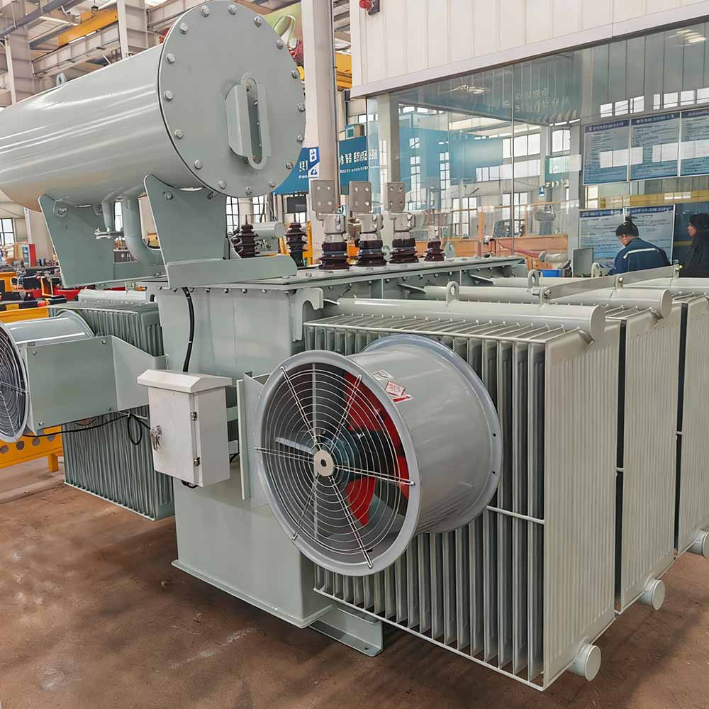
Industrial transformer sizing is a risk-allocation problem disguised as a simple calculation.
Selecting a transformer that is too small can lead to excessive temperature rise, voltage dips, nuisance tripping, restricted plant expansion, and accelerated insulation aging. Selecting one that is unnecessarily large can increase no-load energy losses, raise the available fault current, require larger downstream equipment, and leave the transformer operating inefficiently at light load.
The correct rating is therefore not found by adding every nameplate in a factory and choosing the next available transformer size. It comes from understanding how the facility actually operates.
A reliable sizing process should:
- Create a verified load schedule.
- Convert every load group into kVA.
- Apply justified demand and diversity assumptions.
- Test motor-starting and short-duration peak conditions.
- evaluate harmonic-producing loads.
- Account for temperature, altitude, ventilation, and enclosure conditions.
- Include defined future expansion without arbitrary oversizing.
- Verify fault levels, voltage regulation, switchgear, cables, and protection.
- Select the final standard rating and transformer construction.
Final equipment selection must always be checked by qualified electrical professionals against the applicable utility requirements, project specifications, and local electrical codes.
Оглавление
Why Connected Load Is Not the Same as Transformer Load
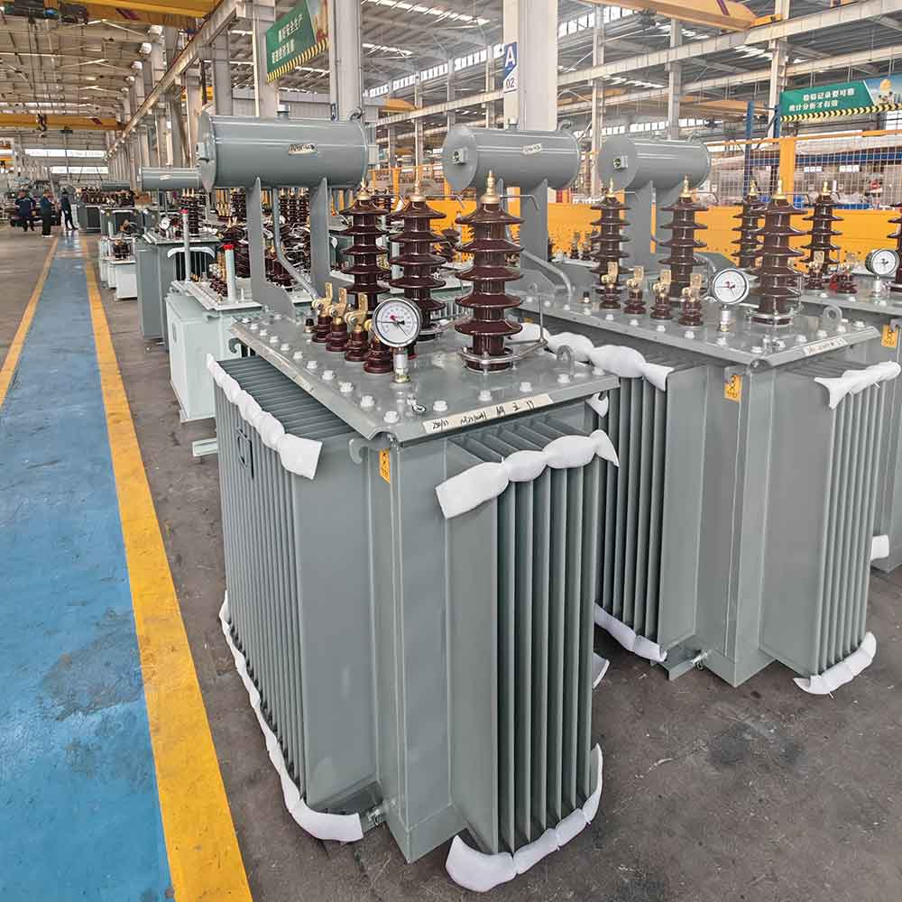
Connected load is the total rating of all equipment electrically connected to the system. It is useful for creating an equipment inventory, but it rarely represents the load that a transformer must supply at one moment.
Consider a plant containing production motors, standby pumps, ventilation systems, electric heating, workshop outlets, lighting, battery chargers, and maintenance equipment. Adding every nameplate assumes that all equipment operates at full output simultaneously. That may be unrealistic.
The opposite error is equally dangerous: applying a single low demand percentage to the entire factory without understanding which loads can overlap.
Industrial transformer sizing should distinguish between the following values:
| Load term | Meaning | Sizing significance |
|---|---|---|
| Connected load | Sum of equipment nameplate ratings | Starting point for the load inventory |
| Maximum demand | Highest coincident demand during a defined period | More relevant than total connected load |
| Demand factor | Maximum demand divided by connected load | Must be based on operating evidence |
| Diversity factor | Sum of individual maximum demands divided by the combined system maximum | Reflects noncoincident equipment operation |
| Load factor | Average load divided by peak load over a period | Helps evaluate utilization and losses |
| Duty cycle | Percentage of time equipment operates in a defined cycle | Important for intermittent processes |
| Critical load | Load that must remain energized during an outage | Determines redundancy requirements |
| Future load | Documented additions expected during the design horizon | Should be quantified rather than guessed |
For an existing facility, interval meter data and operating records are usually more reliable than nameplate totals. For a new facility, the load schedule should be developed with the process designer, mechanical engineer, production team, and electrical engineer.
Start With a Load Schedule, Not a Spare-Capacity Percentage
A useful load schedule provides more than equipment power ratings. It explains how each load behaves.
For every major load or load group, collect:
- Rated kW, kVA, current, and voltage
- Phase and frequency
- True power factor at the expected operating point
- Efficiency, where the load input must be calculated from mechanical output
- Continuous, intermittent, cyclic, or standby duty
- Normal and maximum operating load
- Starting method and starting current
- Number of starts per hour
- Whether similar loads start simultaneously
- Harmonic characteristics
- Essential or nonessential status
- Planned expansion
- Operating schedule or production shift
- Seasonal operating pattern
Standby equipment deserves special attention. A standby pump may not contribute to normal demand if it is mechanically and electrically interlocked with the duty pump. However, it may need to operate during an abnormal condition when other loads are also high.
The load schedule should therefore include at least three scenarios:
- Normal operating condition
- Credible peak operating condition
- Emergency or contingency condition
This scenario-based method produces a more defensible result than multiplying the total connected load by a general percentage.
Convert Industrial Loads to kVA Correctly
Transformers are rated in kVA because their thermal loading is mainly related to voltage and current, while the useful kW delivered to equipment also depends on power factor.
For a single-phase load:
kVA = (V × I) / 1,000
For a balanced three-phase load:
kVA = (√3 × VLL × I) / 1,000
Where:
VLLis the line-to-line voltageIis the line current√3is approximately 1.732
When active power and true power factor are known:
kVA = kW / true power factor
For example, a verified peak load of 500 kW at a true power factor of 0.80 represents:
500 ÷ 0.80 = 625 kVA
The same 500 kW load at a power factor of 0.95 represents approximately:
500 ÷ 0.95 = 526 kVA
This difference is why a transformer should not be selected from kW alone.
Use Input Power, Not Mechanical Output
A motor nameplate may show mechanical shaft output. The electrical input is higher because the motor is not perfectly efficient.
If a motor produces 90 kW of mechanical output at 94% efficiency:
Electrical input = 90 ÷ 0.94 = 95.7 kW
That electrical input must then be divided by the motor’s operating power factor to obtain kVA.
Use True Power Factor for Nonlinear Loads
For sinusoidal loads, displacement power factor may be sufficient. For nonlinear loads, true power factor also reflects waveform distortion. Using only displacement power factor can understate current and transformer heating.
Where loads include variable-frequency drives, rectifiers, uninterruptible power systems, battery chargers, or other power-electronic equipment, use measured RMS current and true power factor whenever possible.
Unbalanced single-phase loads also need phase-by-phase review. A reasonable total three-phase kVA does not guarantee that each winding and the neutral are adequately loaded.
Apply Demand, Diversity, and Duty Cycle Without Hiding Risk
Demand and diversity should describe real plant behavior, not compensate for missing information.
A production line that operates continuously may require a demand factor close to its expected operating output. A maintenance outlet used occasionally may justify a lower contribution. Two mechanically interlocked pumps may not operate together, while two compressors controlled by pressure staging could overlap during recovery.
Use the following evidence, in order of preference:
- Interval metering from the facility
- Process operating sequences
- Equipment control logic and interlocks
- Production schedules
- Data from genuinely comparable facilities
- Documented engineering assumptions
Avoid applying multiple reductions to the same load. For example, reducing motor input through an operating factor and then applying another general demand factor may count the same diversity twice.
A good load schedule makes every assumption visible. If the project later changes, the effect on the transformer rating can then be recalculated without rebuilding the entire study.
Worked Example: From a Factory Load List to a Candidate Rating
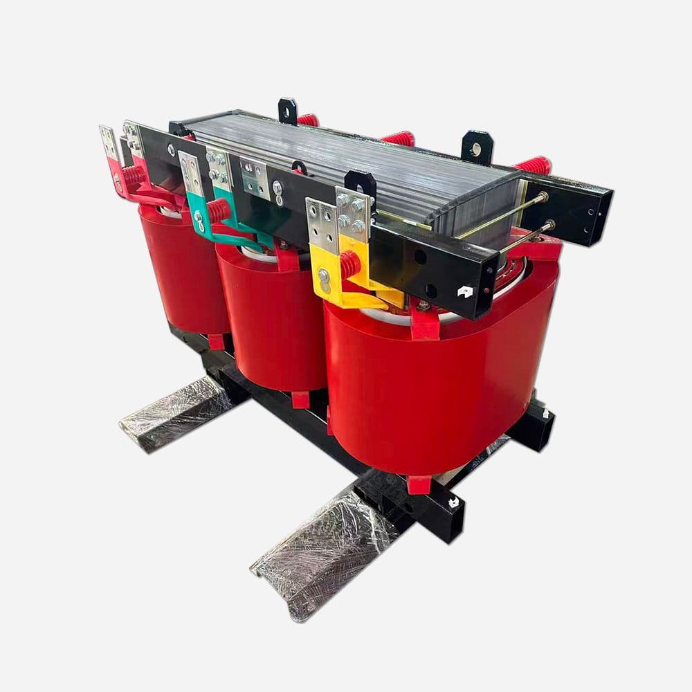
The following example illustrates the method. Its demand factors and power factors are hypothetical and must not be reused without project-specific evidence.
| Load group | Connected load | Illustrative demand factor | Diversified kW | True power factor | Calculated kVA |
| Production motors | 340 kW | 0.75 | 255 kW | 0.86 | 296.5 kVA |
| Pumps and compressors | 180 kW | 0.70 | 126 kW | 0.84 | 150.0 kVA |
| HVAC and ventilation | 120 kW | 0.80 | 96 kW | 0.90 | 106.7 kVA |
| Process heating | 90 kW | 0.90 | 81 kW | 0.98 | 82.7 kVA |
| Lighting and controls | 50 kW | 0.90 | 45 kW | 0.95 | 47.4 kVA |
| Total | 780 kW | — | 603 kW | — | 683.3 kVA |
The arithmetic result is approximately 683 kVA, but that is not yet the required transformer rating.
An 800 kVA transformer might appear acceptable because it exceeds the calculated diversified load. Before accepting it, the engineer still needs to answer several questions:
- Can the largest motor start without an unacceptable voltage dip?
- Can multiple motors restart after a short supply interruption?
- What percentage of the load is nonlinear?
- Is the transformer installed at high altitude or high ambient temperature?
- Is forced cooling required, and can the normal rating be maintained if fans are unavailable?
- Will a planned process addition operate during the current peak?
- Is the 683 kVA result based on a brief peak or a sustained production condition?
- Does the selected impedance maintain acceptable voltage regulation?
- Can the downstream switchgear withstand the resulting fault current?
- Is redundancy required during maintenance or transformer failure?
Suppose the plant has a confirmed future addition of 100 kW at a power factor of 0.90. If that load coincides with the existing peak, it adds approximately 111 kVA:
683.3 + (100 ÷ 0.90) = 794.4 kVA
An 800 kVA rating would then provide virtually no allowance for measurement uncertainty, harmonic heating, environmental derating, or operating changes. A larger standard rating or a different system arrangement may be justified.
If the expansion is only speculative, automatically selecting a much larger transformer may not be the best answer. Reserving a transformer bay, designing expandable low-voltage switchgear, or dividing the plant into modular load centers could offer greater flexibility.
Check Motor Starting Before Accepting the kVA Result
Motor starting is one of the most common reasons a transformer that looks adequate on paper performs poorly in service.
A motor can draw several times its normal current during acceleration. The exact current and duration depend on:
- Motor design
- Driven-machine torque
- Load inertia
- Supply voltage
- Starting method
- Acceleration time
- Number of simultaneous starts
- Transformer impedance
- Upstream system strength
- Cable impedance
- Existing transformer load
Starting current is not simply added to the continuous kVA total as though it were a permanent load. It should be evaluated as a transient condition.
The engineer should calculate the expected voltage dip at the transformer secondary and at the motor terminals. The result must be checked against motor acceleration requirements, contactor holding voltage, process controls, sensitive electronic equipment, and utility limits.
A reduced-voltage starter, soft starter, or variable-frequency drive may reduce the starting disturbance, but each method changes the electrical behavior differently. A drive may reduce motor-starting current while introducing nonlinear current and harmonics during normal operation.
Also examine recovery after a momentary interruption. If several motors automatically restart together, the post-outage condition can be more severe than a normal individual start. Sequential restart logic can sometimes solve this problem without unnecessarily increasing transformer kVA.
Account for Harmonics and Nonlinear Loads
Modern industrial facilities contain more nonlinear loads than many historical demand rules assumed. Common sources include:
- Variable-frequency drives
- Rectifiers
- Uninterruptible power systems
- Battery chargers
- Welding equipment
- Data-processing equipment
- LED power supplies
- Renewable-energy converters
- High-capacity charging systems
Harmonic currents can increase winding eddy-current losses, conductor heating, neutral current, and local hot-spot temperature. A transformer carrying 700 kVA of heavily distorted current may experience different heating from one carrying 700 kVA of nearly sinusoidal motor load.
The load study should identify:
- Percentage of nonlinear load
- Expected current harmonic spectrum
- Total harmonic current distortion
- Triplen harmonics and neutral loading
- Load balance between phases
- Power-factor correction equipment
- Risk of resonance
- Whether harmonic mitigation is included
Possible responses include specifying a transformer evaluated for the harmonic duty, applying a manufacturer-approved derating, changing the winding arrangement, increasing neutral capability, or reducing harmonics at their source. The correct response depends on the measured or calculated spectrum; one universal adjustment factor is not reliable.
When converters form a significant share of plant demand, industrial transformer sizing should be coordinated with a harmonic study rather than treated as a basic kW-to-kVA conversion.
Apply Temperature, Altitude, Ventilation, and Enclosure Conditions
A transformer’s nameplate rating assumes defined service conditions. Actual thermal capability can change when the installation differs from those conditions.
Important environmental inputs include:
- Maximum and average ambient temperature
- Installation altitude
- Indoor or outdoor location
- Степень защиты корпуса
- Room ventilation and air recirculation
- Direct solar exposure
- Dust, humidity, salt, or corrosive contaminants
- Cooling-air inlet temperature
- Proximity to walls or other heat-producing equipment
- Forced-cooling availability
- Seismic and mechanical requirements
At higher altitude, reduced air density can lower the effectiveness of air cooling and affect external insulation performance. A poorly ventilated transformer room can expose equipment to an ambient temperature significantly above the outdoor design temperature.
The manufacturer should confirm the available kVA under the specified site conditions. Avoid applying a generic derating percentage without checking the relevant transformer design and applicable standard.
Сайт IEC 60076-1 general requirements provide the foundation for power-transformer specifications. For mineral-oil-immersed equipment, IEC 60076-7 addresses loading, operating temperature, and thermal aging. Project specifications and national standards may add other requirements.
Select Oil-Immersed or Dry-Type After the Load Is Known
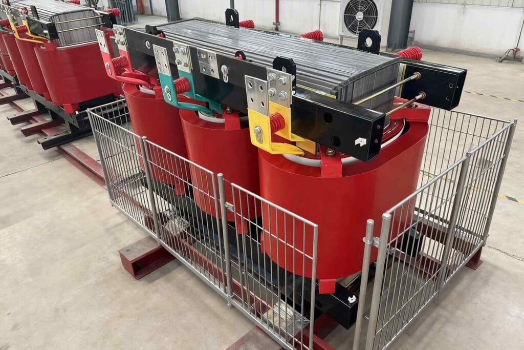
Oil-immersed and dry-type are not competing kVA calculation methods. The project load should first be established, after which the construction is selected for the installation.
An oil-immersed transformer is commonly considered for outdoor substations, continuous industrial loads, and medium- or higher-capacity applications. Its liquid insulation and cooling system provide useful thermal performance, but the installation may require fire separation, liquid containment, environmental controls, and specific maintenance procedures.
An epoxy-resin dry-type transformer can suit indoor installations and locations where avoiding a liquid insulating medium is important. Ventilation, enclosure design, contamination, acoustic requirements, and room temperature remain critical. The applicable technical framework can include IEC 60076-11 for dry-type transformers.
The selection should consider:
| Decision factor | Oil-immersed | Dry-type |
| Typical location | Frequently outdoor or in a dedicated transformer area | Frequently indoor |
| Cooling medium | Insulating liquid and surrounding air | Air, with natural or forced ventilation |
| Building integration | Requires appropriate containment and fire strategy | Requires sufficient ventilation and clearances |
| Environmental exposure | Outdoor design can suit changing weather conditions | Enclosure must match dust, humidity, and contamination |
| Maintenance planning | Includes liquid condition and sealing-system checks | Focuses on cleaning, ventilation, connections, and insulation condition |
| Project decision | Based on load, site, safety, and lifecycle requirements | Based on load, site, safety, and lifecycle requirements |
Review the available power transformer options only after the electrical and environmental requirements are defined.
Check Short-Circuit Duty, Voltage Drop, and Protection
A transformer rating cannot be finalized independently of the rest of the power-distribution system.
For a three-phase transformer, rated secondary current is approximately:
I = (kVA × 1,000) ÷ (√3 × secondary voltage)
At 400 V:
- An 800 kVA transformer has a rated secondary current of approximately 1,155 A.
- A 1,000 kVA transformer has a rated secondary current of approximately 1,443 A.
This current affects busbars, cables, breakers, metering, and protection.
Transformer impedance also affects voltage regulation and available short-circuit current. As a simplified terminal estimate that ignores upstream and conductor impedance:
Short-circuit current ≈ full-load current × 100 ÷ impedance percentage
This shortcut is useful for an initial check but is not a substitute for a complete short-circuit study.
A larger transformer can increase available fault current. Selecting the next kVA rating without recalculating the system may exceed the withstand or interrupting capability of existing equipment.
The final design should coordinate the transformer with:
- Medium-voltage protection
- Высоковольтные распределительные устройства
- Low-voltage main switchgear
- Busbar withstand ratings
- Cable thermal and short-circuit ratings
- Breaker interrupting capacity
- Relay and fuse settings
- Earth-fault protection
- Selective coordination
- Arc-flash risk assessment
- Grounding and neutral arrangement
IEC 60076-5 addresses a power transformer’s ability to withstand the effects of external short circuits. Installation-level protection still has to be engineered for the complete system.
For U.S.-based projects, the relevant workplace requirements and safe work practices should also be reviewed using official electrical power safety resources. Other countries will have their own governing regulations.
Plan Future Capacity Without Automatically Oversizing
“Add 20%” is not a complete expansion strategy.
Future capacity should be divided into three categories:
- Committed expansion: Equipment has been selected or approved and its load is reasonably known.
- Probable expansion: The process is likely, but its operating profile still contains uncertainty.
- Possible expansion: Space may be developed later, but no defined load exists.
Committed expansion can be included directly in the load scenarios. Probable expansion should be evaluated through alternatives. Possible expansion may be better addressed through physical space, spare switchgear sections, cable routes, or a future transformer bay.
Excessive oversizing has consequences. Core losses occur whenever an energized transformer is connected, even when the secondary load is low. Load losses increase approximately with the square of current. The expected annual load profile should therefore be compared with guaranteed no-load and load losses rather than judging efficiency only at peak demand.
Efficiency requirements also differ by market. The U.S. Department of Energy’s distribution transformer information illustrates how transformer definitions and efficiency obligations can be jurisdiction-specific. International projects should identify the destination-country requirements at the RFQ stage.
The better question is not “How much spare percentage should be added?” It is “Which future loads are credible, when will they operate, and will they coincide with today’s peak?”
Decide Between One Transformer and a Redundant Arrangement
Some plants need more than additional kVA; they need operational resilience.
A single large transformer may offer a straightforward system arrangement, but maintenance or failure can interrupt the entire supplied process. Two transformers may allow load separation, scheduled maintenance, or continuity for critical operations.
However, installing two transformers does not automatically create N+1 redundancy. If both are required to carry the normal load, loss of either transformer will still require load shedding.
When evaluating a multi-transformer arrangement, consider:
- Normal load per transformer
- Critical load after one unit is unavailable
- Permitted emergency loading
- Bus coupler arrangement
- Automatic or manual transfer
- Protection coordination
- Fault contribution with transformers operated in parallel
- Planned maintenance sequence
- Matching voltage ratio and tap position
- Compatible vector group and phase displacement
- Similar percentage impedance
- Circulating-current risk
- Space for future additions
IEC 60076-8 discusses transformer application topics including connections, system fault currents, voltage variation, and parallel operation.
For a process that cannot tolerate a total shutdown, architecture may be more important than simply moving from one standard kVA rating to the next.
Industrial Transformer Sizing RFQ Checklist
A detailed RFQ enables the transformer manufacturer and EPC engineering team to verify the proposed rating rather than quote against incomplete data.
| Required information | What to provide | Why it matters |
| Primary voltage | Nominal voltage and allowable variation | Determines winding and insulation requirements |
| Secondary voltage | Required no-load and loaded voltage | Affects ratio, current, and regulation |
| Frequency and phase | 50/60 Hz, single or three phase | Fundamental design parameter |
| Load schedule | Connected, demand, peak, and critical loads | Establishes required kVA |
| Power factor | Expected true power factor by load group | Converts kW to actual kVA |
| Largest motor | Rating, starting current, method, and acceleration time | Required for voltage-dip analysis |
| Operating sequence | Simultaneous loads, interlocks, and restart logic | Establishes credible peak demand |
| Nonlinear loads | Drives, rectifiers, chargers, UPS, and harmonic data | Identifies additional heating |
| Future expansion | Defined kW/kVA, power factor, and start date | Prevents arbitrary margin selection |
| Site conditions | Temperature, altitude, humidity, dust, and corrosion | Determines environmental design and derating |
| Установка | Indoor/outdoor, enclosure, ventilation, and clearances | Influences transformer construction and cooling |
| System study data | Available fault level and required transformer impedance | Supports protection and short-circuit design |
| Connection | Vector group, grounding, neutral, and phase arrangement | Ensures system compatibility |
| Tap requirements | Tap range, step size, and off-circuit or on-load operation | Supports voltage management |
| Метод охлаждения | Natural or forced cooling and required ratings | Defines thermal capability |
| Efficiency requirements | Destination-country rules and guaranteed losses | Supports compliance and energy evaluation |
| Applicable standards | IEC, national, utility, and project standards | Prevents specification conflicts |
| Reliability target | Single unit, parallel units, or N+1 requirement | Determines system architecture |
| Documentation | Drawings, test reports, certificates, and data sheets | Supports review and commissioning |
Providing this information also helps coordinate the transformer with cables, switchgear, protection, civil works, ventilation, and commissioning.
Common Industrial Transformer Sizing Mistakes

Adding All Nameplates Without Studying Coincidence
This frequently produces an oversized transformer and hides how the plant actually operates.
Applying One Demand Factor to Every Load
Motors, heating, lighting, intermittent machinery, and standby equipment do not have identical operating behavior.
Converting kW to kVA With an Assumed Power Factor
Actual power factor can change with motor loading and may be significantly affected by nonlinear equipment.
Ignoring Motor Restart Conditions
A transformer may handle normal production but fail to support simultaneous restart after a supply interruption.
Treating Harmonics as Extra kW
Harmonic risk is related to current spectrum and additional losses, not merely an arbitrary addition to active power.
Forgetting Environmental Derating
A rating established for standard service conditions may not be available in a hot, high-altitude, or poorly ventilated installation.
Selecting kVA Before Checking Fault Current
Increasing transformer capacity can require higher-rated switchgear and revised protection settings.
Adding Unverified Future Capacity
Undefined expansion can cause years of light-load operation without providing a genuinely usable expansion plan.
Specifying Only Voltage and kVA
Two transformers with the same voltage ratio and kVA can have different impedance, cooling, loss, connection, enclosure, and environmental characteristics.
ЧАСТО ЗАДАВАЕМЫЕ ВОПРОСЫ
What size transformer does a factory need?
A factory needs a transformer whose usable rating exceeds the highest credible coincident kVA after motor starting, harmonics, environmental conditions, future committed loads, voltage regulation, and reliability requirements have been checked. Connected load alone is not enough to select the rating.
Can a 500 kW factory use a 500 kVA transformer?
Not normally if 500 kW represents the actual peak. At a power factor of 0.90, 500 kW requires approximately 556 kVA before other sizing conditions are considered. At a power factor of 0.80, it requires 625 kVA. The engineer must also determine whether 500 kW is connected load, average load, or verified maximum demand.
Can an 800 kVA transformer supply 800 kW?
Only at a power factor of 1.0 would 800 kVA correspond mathematically to 800 kW. At a power factor of 0.90, 800 kVA corresponds to 720 kW. Actual permissible loading also depends on temperature, cooling, harmonics, voltage, load duration, and the transformer design.
How much spare capacity should be included?
There is no universal spare-capacity percentage. Include quantified committed expansion and an allowance appropriate to the accuracy of the load study. For uncertain long-term expansion, compare a larger transformer with modular substations, reserved switchgear sections, or a future transformer bay.
Is operating a transformer at 80% load always ideal?
No. The preferred operating range depends on the load profile, no-load and load losses, ambient conditions, reliability strategy, and expected expansion. A single percentage cannot optimize every transformer or industrial facility.
Does motor starting always require a larger transformer?
Not always. The result depends on motor size, starting method, transformer impedance, upstream system strength, acceleration time, and allowable voltage dip. Sequential starting or an appropriate starter may resolve the transient condition, but the complete system must be studied.
Does altitude affect transformer sizing?
Yes. Reduced air density at higher altitude can reduce cooling effectiveness and influence insulation clearances. The transformer manufacturer should confirm the available rating and design requirements for the project altitude.
Can power-factor correction reduce the required transformer kVA?
Improving power factor can reduce reactive current and release transformer capacity. However, correction equipment must be coordinated with changing load, switching conditions, harmonic distortion, and resonance risk. Transformer sizing should not assume future correction equipment without a verified design.
Заключение
Accurate industrial transformer sizing begins with real operating data, not a generic safety percentage. The engineer must convert the load to kVA, establish credible demand scenarios, study motor starting and harmonics, apply site conditions, and coordinate the result with protection, switchgear, efficiency, and future expansion.
The numerical load calculation identifies a candidate rating. The system study determines whether that candidate will operate safely and reliably.
For a project-specific transformer recommendation, prepare the load schedule, primary and secondary voltages, largest motor data, harmonic load details, site conditions, future expansion, and applicable standards. Then contact the engineering team to evaluate the required transformer rating and its integration with the complete industrial power-distribution system.